Progressive cavity pump performance parameters usually refer to flow, discharge pressure, suction pressure, rotational speed, pump input power (shaft power), medium characteristics, medium temperature and medium viscosity. The flow is affected by the rotational speed and the viscosity of the medium, and the viscosity of the medium also affects the input power of the pump. The choice of rotational speed has a great relationship with the viscosity of the medium, and also affects the suction performance of the pump. The relationship between these parameters must be considered when designing the pump.
Flow
Flow refers to the amount of medium delivered by the pump per unit time or the amount of medium discharged per revolution of the pump. The volume flow is represented by Q , and the mass flow is represented by Qz . The relationship between mass flow and volume flow is:
Q = Qz / ρ
where ρ—medium density (kg/m³).
When the rotor rotates once, the medium moves the stator one lead T along the axial direction, so the rotor rotates once, and the volume of the medium conveyed by the pump is 4eDT. So when the rotor speed is n, the theoretical flow per second of the single screw pump is Q1 :
Q1 = 4eDTn / 60 ——– ( 2 – 45 )
In fact, there is an interference between the rubber stator and the rotor, which will inevitably cause deformation of the stator rubber. Therefore, the actual theoretical flow rate is smaller than the theoretical flow rate calculated in the above formula. To get the exact actual theoretical flow value, after the rotor is installed in the stator, a section of length T can be cut off, filled with water, and then the volume of injected water can be measured.
The actual flow rate Q of the pump is lower than the actual theoretical flow rate Q1 , because when the rotor moves in the stator, some medium will always flow back to the suction chamber through the unsealed matching gap under the action of the discharge pressure. The larger the gap, the more leakage, the greater the pressure difference between the two ends of the sealing chamber, and the greater the leakage. In addition, the inclusion of gas in the process of medium transportation will also cause the flow rate to decrease.
If q is used to represent the flow rate of leakage in the pump, the actual flow rate Q of the pump is:
Q = Q1 – q ——– ( 2 – 46 )
Obviously, when the same pump is transporting media of different viscosity, even under the same suction pressure, discharge pressure and same rotation speed, its leakage is different. Our country’s current standard stipulates that the flow rate Q is the test medium with clean water as the standard. Because the same pump can transport media of different viscosities, it is impossible for companies that produce pumps to test all the media actually used by the pump, so almost all the test benches of my country’s progressive cavity pump manufacturers use clean water as the test medium, and then convert according to the viscosity of the medium actually delivered by the pump. The conversion formula adopts an empirical formula, which will have errors with the actual situation, and even the same conversion formula has different errors in the conversion of different medium viscosities. This is because these empirical formulas are based on tests, and different empirical formulas will be obtained depending on the amount of the test, the accuracy of the collected test data, the difference in the single screw pump used for the test, and the difference in the test conditions. , the conversion and the actual error naturally cannot be the same.
The conversion formula for the relationship between flow rate and viscosity provided by Japan’s KOSAKA Research Institute is:
Q i = Q1 – ( Q1 – Q H2 O ) K Q ——– ( 2-47 )
In the formula:
- Qi ——— converted volume flow;
- Q1 ——— Theoretical flow rate in clear water medium;
- QH2O ——— Actual flow when clear water medium;
- KQ ——— Flow correction coefficient, its formula is:

where:
- vi is the actual viscosity of the medium used;
- vH2O is the viscosity of clean water.
Conversion formula introduced by Russia is:

That is, the relationship between leakage and viscosity can be regarded as:

In the formula:
- qi ——– The amount of leakage after conversion of the medium used;
- qH2O ——– The amount of leakage during the clean water test.
On the surface, the relationship between flow and speed seems to be directly proportional, that is:

In fact, it is not, because under the same conditions, the speed of rotation is different, and the leakage amount q inside the pump is also different. As the speed of rotation decreases, the leakage will increase.
When the actual speed ni does not match the rated speed ne, the measured flow rate Qi can be converted to the flow rate Qe at the rated speed ne by the following empirical formula:

It can be seen from the above description that the leakage amount q is an important factor affecting the performance of the pump. Therefore, the volumetric efficiency ηv has become an important indicator of the performance of the pump. The volumetric efficiency ηv is the ratio of the output power Pu = pQ and the theoretical power P1 = pQ, that is, the ratio of the actual flow to the theoretical flow:

Chinese standard JB/T 8644-2007 stipulates that one of the requirements for qualified products is the ηv of the pump at no load, which shall not be lower than 96%.
Pressure difference
The pressure difference p of the pump refers to the difference between the discharge pressure pd and the suction pressure ps.
For positive displacement pumps, the so-called discharge pressure is actually the back pressure of the pump, that is, the total resistance of the pump outlet piping system, which is completely different from the concept of centrifugal pumps.
Therefore, the pressure difference of the progressive cavity pump has nothing to do with the properties of the conveyed medium; However, it should be noted that the greater the viscosity of the conveyed medium, the greater the resistance in the outlet piping system.
IIf the working length of progressive cavity pump contains multiple sealing cavities, that is, in the case of multistage, as mentioned above, it is desirable that there is also a pressure difference Δp at both ends of each sealing cavity, and the pressure difference of each sealing cavity is equal, which is the most ideal. When the pump is running, the pressure in the seal chamber increases from suction pressure to discharge pressure. Theoretically, the increase of pressure should be directly proportional to the distance that the medium in the seal moves in the stator, that is to say, the more stages contained in the working length of the pump, the greater the pressure difference Δp at both ends of the working length.
Therefore, when designing a single screw pump, after the rated discharge pressure pd and suction pressure ps are determined, it is necessary to correctly select the pressure difference Δp of the first stage, so as to determine how many stages the pump should be designed into, and determine the size l of the matching working length of the stator and rotor of the pump, that is:

Theoretically, it is impossible to accurately determine the value of Δp, not only because it is related to the material of the stator, the interference or clearance value of the fit between the stator and the rotor, and the tooth profile accuracy of the stator and the rotor, but also because, as described above, the Δp value of each stage may be completely different due to the inconsistent fit between the stator and the rotor.
The design is still based on the ideal state, assuming that the pressure difference Δp at all levels is the same. In the case of using rubber stators in my country, the pressure difference Δp of the first stage is usually selected for the so-called non-abrasive medium at about 0.6Mpa. In this state, it is more appropriate to comprehensively consider the efficiency and life of the pump. For slightly abrasive media, the Δp of the first stage is about 0.5Mpa; for medium abrasive media, the pressure difference Δp of the first stage is about 0.3Mpa; for the severely abrasive medium, the pressure difference Δp of the first stage is usually selected not more than 0.2 Mpa is appropriate.
Speed
For progressive cavity pumps to work reliably, the rotational speed must be limited. The main factors affecting the choice of speed are as follows:
1. Suction performance
The higher the speed of the pump, the greater the flow. The speed not only affects the loss in the pump suction chamber, but also when the speed increases to a certain extent, the medium under the suction pressure will have no time to enter or fill the open sealing chamber, resulting in a certain degree of vacuum, and a large amount of dissolved gas will be precipitated from the transmission medium, It is distributed in the medium in the form of bubbles and becomes emulsion, which leads to the reduction of flow and even makes the pump unable to work normally.
If the pressure drops to the saturated vapor pressure of the conveyed medium at a certain temperature, cavitation will occur in the pump, the continuity of the conveyed medium will be damaged, and the flow will drop sharply.
When the air bubbles generated by cavitation are sent to the high pressure area, the air bubbles collide and rupture at a high speed, causing hydraulic shock, producing large vibration and noise, causing local damage to the material, and even damage to the pump, which cannot operate normally. . Therefore, the rotational speed is limited by the suction conditions.
The relationship between suction performance and rotational speed can be regarded as related to the axial flow velocity of the medium, and the axial flow velocity vz (m/s) of the medium is:
vz = nT/60 ——– ( 2-52 )
The geometric height of the suction, the friction resistance of the medium in the suction pipeline, the characteristics and temperature of the medium all limit the allowable speed of the pump. From formula (2-52), it can be seen that the lower the pump speed, that is, the smaller the axial flow velocity of the medium, the better the suction performance of the pump. The temperature of the medium directly affects the saturated vapor pressure of the medium and the viscosity of some media.
When compiling JB / t8644-1977 “types and basic parameters of single screw pump”, the axial velocity of medium shall not be greater than 4 ~ 4.5m/s.
2. Viscosity
When the viscosity of the medium increases, it will not only make it more difficult for the medium to enter the seal cavity under the suction pressure because of the increased resistance, but also increase the mechanical loss caused by the shearing effect of the rotor on the medium. Therefore, when the progressive cavity pump operation, if the greater the viscosity of the medium, the lower the speed should be selected.
Ltd. (TAIKO KIKAI) recommended progressive cavity pump medium viscosity and the relationship between the selected speed as shown in Table 2-5.
The relationship between the recommended medium viscosity and the selected speed of Bornemann Germany is shown in Table 2-6.
Table 2-5 The relationship between the recommended medium viscosity and the selected rotational speed of TAIKO KIKAI
| Dynamic viscosity/(Pa-s) | Pump speed/(r/min) |
|---|---|
| 0.001~1.0 | 400~700 |
| 1.0-10 | 200~400 |
| 10~100 | <200 |
| 100~1000 | <100 |
Note: The viscosity of pure water is 1mPa-s=0.001Pa-s.
Table 2-6 Relationship between the recommended medium viscosity and the selected speed of Bornemann
| Dynamic viscosity/(Pa-s) | Pump speed/(r/min) |
|---|---|
| 1-1000 | 400-1000 |
| 1000~10000 | 200-400 |
| 10000~100000 | <200 |
| 100000~1000000 | <100 |
Note: The viscosity of pure water is 1mPa-s=0.001Pa-s.
At present, many products in China choose the pump speed is usually greater than the above recommended selection of values, such as power viscosity of 0.001 ~ 1.0 Pa – s, usually selected speed of 600 ~ 1200r / min, etc..
The selection of pump speed according to medium viscosity is also related to many other factors, such as the interference between stator and rotor, the correct tooth shape of stator and rotor, the impurity content of medium and the performance of rubber.
3. Abrasiveness of the medium.
The abrasiveness of the medium directly affects the wear resistance of the rotor and stator, i.e., the service life. The more “harsh” the medium (here only refers to the impurities contained, lubricity and fluidity, etc.), the easier the rotor and stator are bound to wear, and the higher the pump speed, the faster the wear. Therefore, the pump speed will also be limited by the abrasiveness of the transport medium. Some foreign manufacturers recommend the relationship between the abrasiveness of the medium and the selected pump speed is shown in Table 2-7.
Table 2-7 relationship between wear resistance of recommended medium and selected pump speed
| Abrasiveness | Examples of media | Rotational speed/(r/min) |
|---|---|---|
| Minor | Water, oil, slurry, minced meat, soap solution, paint | 400~600 |
| Fair | Industrial wastewater, pigments, slurries, suspensions, mortars, oil wells | 200~400 |
| Severe | Coal and water slurry, clay, lime slurry, clay, oil well | 50-200 |
4. The sensitivity of the structure to rotational speed when the medium is an emulsion liquid.
As mentioned earlier, the pump conveys the medium in order to separate the oil from the oily water, the requirements do not make the medium emulsification increased, the pump must be required to run at low speed, usually the speed does not exceed 200 / min.
Inhalation performance
Influence the suction performance of the progressive cavity pump has been described in the third point of speed in this paper. It can also be seen from equation (2-52) that the suction performance is related to the rotational speed n and the stator lead T. The lower the speed, the smaller the stator lead, the better the suction performance. However, the size of the lead T cannot be reduced indefinitely, the smaller the T, the same flow rate will have to increase the lateral size of the pump, and will be limited by the processing possibilities. In addition, the higher the viscosity of the medium, the greater the loss in the suction line, and the poorer the suction performance.
Progressive cavity pump inlet is higher than the liquid level of the medium, that is, the pump suction cavity with vacuum non-inverted, the design should pay particular attention to the requirements of the suction performance, in order to avoid the suction pipeline loss (the sum of geometric height and pipeline resistance head loss) large and cause cavitation of the pump. This is to consider the allowable suction vacuum, i.e. the allowable cavitation margin [NPSH]. The relationship between the allowable cavitation margin and the necessary cavitation margin NPSHr, is usually:
[NPSH] = (1.1 ~1.3 NPSHr, or [NPSH] = NPSHr + K
Where k – safety margin value, usually K is taken as 0.3m.
Single screw pump has very good suction performance, usually in the transport of clear water, the highest suction height of about 6m, single screw pump under certain conditions the highest suction height can reach 8.5m, and has the ability to self-priming. When the conveyed medium is high viscosity, the inlet pipe system of the pump should be arranged so that the inlet pressure is positive, that is, the pump is in the position of backflow, even in the suction chamber of the pump needs to be designed with spiral thrusters and other devices, so that the medium can enter the sealing chamber smoothly.
Pump input power (shaft power), output power and efficiency
The power of a progressive cavity pump usually refers to the input power, that is, the power transmitted from the power source to the pump shaft, so also known as shaft power, expressed in Pr (kW).
Pr = pQ / (η x 103) ——– ( 2-53 )
In the formula:
- η ———- total efficiency of the progressive cavity pump (%);
- P ——— full pressure (Pa);
- Q ——- volumetric flow rate (m³/s)
The effective power of the single screw pump, also known as the output power, is expressed in Pu:
Pu = pQ / 103) ——– ( 2-53 )
The above formula (2-53) and formula (2-54) refer to the power value when the medium is the working condition of clear water, if the non-clear water medium, it is necessary to consider the heaviness of the transported medium γ.
The power input from the power source to the pump shaft Pr, divided by the sum of the various mechanical losses existing in the pump during operation, the remaining power is the theoretical power of the pump P1 = pQ1. It can be seen that the mechanical efficiency ηm is the ratio of theoretical power and input power, that is.
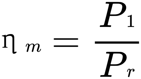
Mechanical efficiency ηm is an important indicator of the performance of the pump, that is, the size of the mechanical loss in the pump, which includes not only the friction loss between the rotor and stator and the friction loss between the bearing, shaft seal, universal joint and the media, but also the media vortex movement and the media in the pump flow of local resistance and friction resistance caused by the power loss.
Pump input power Pr value and the media situation is very relevant, the greater the viscosity, or contain more impurities, the greater the mechanical losses. Therefore, the test to determine the input power in addition to the relevant standard conditions (progressive cavity pump to room temperature clear water as the standard value of the test conditions), the input power must be pointed out in the medium for what viscosity value of the value. As it is usually not possible to use the actual medium to do the test, so in the use of clear water test and then converted, the conversion between the two is the use of empirical formulas, and the actual situation has a certain difference.
The empirical formula for converting pump input power Pr by Kosaka Research Institute (KOSAKA), Japan is:
Pr = Pr(H2O)KN ——– ( 2-53 )
In the above formula:
- Pr ———- the power input of the actual medium;
- Pr(H2o) ———- the pump’s transmission power when clear water;
- KN – transmission power correction factor, the recommended relationship between the proportion of mud in the medium and the KN value is: below 10% KN take 1.1, 15% take 1.15, 20% take 1.2.
JB/T 8091 stipulates that for clear water media, when the medium speed and the rated value do not match, the input power of the pump is converted according to the following formula: Pre=Pri ▪ ne / ni
The power P of the usual supporting power source of our enterprises is taken as: P = KPr ——— (2-57)
In the formula, K = 1.05 ~ 1.2.
The above recommended K value is in the stator and rotor with the normal amount of interference, it should be noted that: the starting torque in the pump no-load operation is generally not large for lubricating oil media, non-lubricating media will be larger.
But the pump in a long time at rest, will cause the rubber stator and rotor between the medium lubrication film extrusion or even disappear, resulting in the stator and rotor surface close to the dry friction state, so that the starting torque will be greatly increased, and even reach the full load several times.
This situation is not only related to the length of time the pump is at rest, but also with the amount of stator and rotor interference, the length of the engagement line, the roughness of the rotor and stator and the coefficient of friction and rubber hardness, etc..
These rotor and stator running friction loss increase of all factors can cause excessive starting torque, and even make the pump can not start.
The total pump efficiency η is the ratio of effective power to actual power, i.e., the ratio of pump output power Pu and input power Pr.
From equation (2-53) and equation (2-54), the total efficiency η of the progressive cavity pump is