Installation
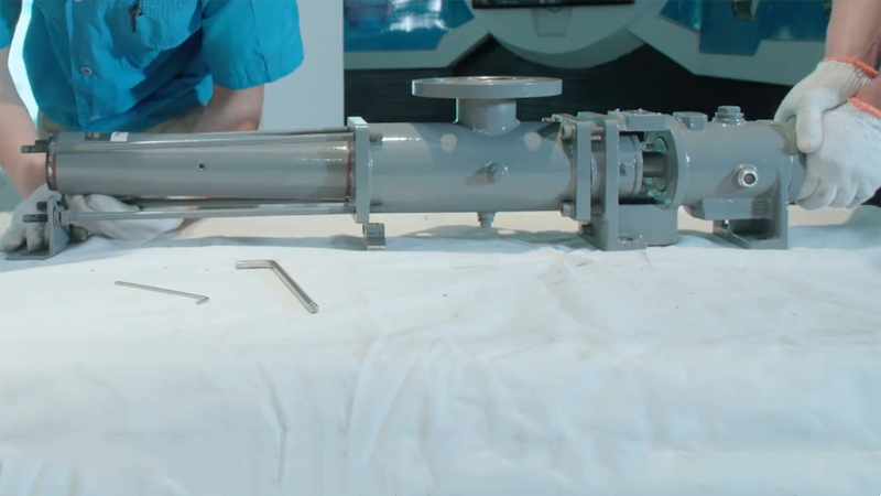
- When assembling the pump, the relevant parts that need to be lubricated (such as bearings, universal joints, etc.) must be filled with grease, usually 2/3 of the cavity volume.
- Check whether the connection parts of the unit are firmly fixed.
- The pump unit (including the independently installed pump, reducer and prime mover) should have a firm and solid foundation, and the unit should be firmly fixed on the foundation to prevent violent vibration during operation.
- Check whether there is a certain gap between the couplings and strictly control the alignment of the two shafts. The runout outside the coupling should not exceed 0.1mm.
- When designing the pipeline of the pump, it should be considered that there is a space larger than the length of the stator at the pump outlet and the pipeline is a detachable structure, which is convenient for maintenance and replacement of the stator.
- Correctly identify the inlet and outlet of the progressive cavity pump before connecting the inlet and outlet pipelines.
Start-up
- Before starting, check whether the connection between the suction pipe section and the instrument connector is sealed.
- Before starting for the first time or after disassembling and assembling, or if the pump has not been started for a long time or the medium in the pump has been removed after use, the suction chamber should be filled with medium, and the pump shaft should be rotated by hand or tool for several revolutions before starting. In order to prevent the pump from starting when there is no medium or only a small amount of medium in the pump, it is necessary to have a medium lubricating liquid film on the surface between the stator and the rotor to avoid dry friction between the stator and the rotor, resulting in damage to the stator or excessive starting torque, which will make the pump unable to start or reduce the suction performance of the pump.
- To transport the medium with high viscosity, the spacer layer of the pump shall be heated before starting to reduce the viscosity of the residual medium in the pump and facilitate starting.
- Check the steering of prime mover to prevent reversal.
- Before starting, all valves on the inlet and outlet pipes should be opened, and the piping system must be unblocked.
Operation
- Check whether the maximum bearing temperature exceeds the temperature specified in the product manual.
- Check whether the shaft seal leakage exceeds the requirements specified in the product manual.
- Pay attention to the indicated value of the vacuum pressure gauge on the inlet pipeline, the pointer should not shake violently, and check whether the flow pipe of the vacuum pressure gauge is installed correctly.
- Pay attention to whether the noise and vibration of the pump are abnormal, and stop immediately if cavitation occurs.
- Pay attention to whether there is a sudden change in the flow and pressure of the pump, and check in time.
Downtime for maintenance
- After the power is cut off, the suction valve and discharge valve should be closed.
- For pumps that transport high viscosity, particle-containing or corrosive media, the media in the pump should be drained after shutdown and cleaned to prevent deposition or damage to the pump.
- When transporting media related to human health such as food and medicine, the media in the pump should be exhausted after the machine is stopped and rinsed, leaving no residual media to avoid the breeding of bacteria.
- If the ambient temperature reaches or is lower than the freezing temperature of the medium, drain the medium in the pump after shutdown to prevent the pump from freezing crack.
- When the pump is out of use for a long time, the medium in the pump should be exhausted, and a little lubricating oil should be injected, and the pump shaft should be rotated by hand or tools. It is best to remove the rotor and apply grease to protect it.
- The rubber stator is not allowed to be directly exposed to sunlight or in an environment of minus 20°C to avoid damage. Pay attention to the validity period of the stator, and do not use an aging stator.
- When replacing the stator, it is usually only necessary to remove the discharge chamber and stator. After cleaning the rotor, drip lubricating oil or grease on the rotor surface and the inner spiral surface of the stator, and then install the stator.
General faults and troubleshooting methods (see Table 2-8)
Table 2-8 General faults and troubleshooting
| Faults | Causes | Exclusion method |
|---|---|---|
| Difficulty starting | 1. The pump is not filled with medium before starting or the pump has not started for a long time. 2. Medium solidification in pump. 3. The interference fit between the rubber stator and the rotor is too large. 4. Shaft seal packing is too tight. 5. Input voltage is too low. 6. Excessive starting torque. | 1. Fill the suction chamber with medium and rotate the pump shaft for several revolutions. 2. Heat pump to reduce medium viscosity. 3. Replace the parts with proper interference. 4. Adjust the tightness of the packing gland. 5. Start after adjusting the voltage to normal. 6. Check and adjust the outlet valve or turn the pump shaft by hand and tools or increase the power of the power source. |
| Abnormal vibration and noise after startup | 1. Cavitation occurs. 2. The pump is not firmly installed. 3. Damage or lack of lubricating oil of reducer gear. 4. Coupling coaxiality error is large. 5. Damaged parts such as universal joints or bearings in the pump. | 1. Check the suction pipeline and oil seal, and do not leak air; check whether the inlet valve leaks air or is fully opened; check the filter and suction pipeline to remove blockage; the diameter of the suction pipeline is too small, replace it; or reduce the speed to adapt to the viscosity of the medium or heat the medium to reduce the viscosity; increase the medium level. 2. Re-installed. 3. Replace damaged parts or add lubricating oil. 4. Correction of the coaxiality of the coupling. 5. Check pump parts, replace bad parts. |
| Zero flow or flow less than normal | 1. The power source rotates in the wrong direction. 2. The inlet and outlet pipes are connected reversely. 3. Medium viscosity is too high. 4. The inlet pipe is too thick 5. Rubber stator is worn 6. The filter screen is blocked or some rotor flow channels are blocked by large particle impurities. 7. Safety valve not closed. 8. The speed is lower than the specified value. | 1. Change the rotation direction of the power supply. 2. Correct the direction of the connecting pipe. 3. Heat pump to reduce viscosity. 4. Replace the inlet pipe. 5. Replace damaged parts. 6. Remove impurities. 7. Adjust the safety valve. 8. Adjust the speed |
| Power source overload | 1. The pressure gauge is inaccurate or the outlet pipeline is blocked, causing the discharge pressure to exceed the specified value. 2. The operating pressure exceeds the specified value. 3. The pump speed exceeds the specified value. 4. The viscosity of the medium increases. 5. The fit interference between stator and rotor is too large. 6. Parts in the pump are damaged, which increases the running resistance. 7. The power grid is abnormal. | 1. Replace the pressure gauge or check the outlet line. 2. Adjust the discharge pressure. 3. Adjust the speed. 4. Reduce viscosity. 5. Replace parts with proper interference. 6. Check and replace damaged parts. 7. Check and adjust the power grid. |
| The shaft seal is overheated or the shaft seal leakage exceeds the standard. | 1. Shaft seal is damaged. 2. The packing is pressed too tightly. 3. Medium temperature too high. 4. Excessive leakage caused by medium solidification. | 1. Replace the damaged shaft seal parts. 2. Adjust the tightness of packing gland. 3. Reduce the medium temperature or replace the shaft seal that can withstand this high temperature. 4. Heat pump to reduce medium viscosity. |
| Bearing temperature rise too high | 1. The bearing is damaged or the bearing is out of service. 2. Insufficient lubricating oil in the bearing or lubricating oil leakage. 3. Too much lubricating oil in bearing pedestal. 4. The temperature of the conveying medium is high; the high temperature is transmitted to the bearing; and the pump type is not selected properly. | 1. Replace the bearing. 2. Add lubricating oil or solve the leak. 3. Reduce lubricating oil. 4. Replacing a pump of a construction type suitable for conveying high temperature media. |
| The pressure of the pump does not reach the specified value | 1. Pressure gauge is inaccurate. 2. The outlet valve is faulty. 3. Severely worn stator or rotor. | 1. Replace the pressure gauge. 2. Repair or replace outlet valve. 3. Replace parts. |